
Activity: Gadget Anatomy
Understanding Machines
Identify and sketch the simple machines that are combined to create a gadget to better understand how it works.
Leonardo's Machines
Leonardo experimented with machines and made changes to improve how they worked. Though these simple machines were in common use for centuries before Leonardo's time, he experimented with them and made changes to improve how they worked. He also combined them in many exciting new ways to create machines and inventions that had never been seen before.
The following simple machines were common in Leonardo's time. Each one makes work easier to do by providing some trade-off between the force applied and the distance over which the force is applied.
- Wheel and Axle: A wheel or spoke is locked to a central axle so that when one is turned the other must turn. A longer motion at the edge of the wheel is converted to a shorter more powerful motion at the axle. In reverse, a short powerful force at the axle will move the wheel's edge a greater distance.
- Pulley: A single pulley simply reverses the direction of a force. When two or more pulleys are connected together, they permit a heavy load to be lifted with less force. The trade-off is that the end of the rope must move a greater distance than the load.
- Wedge: A wedge converts motion in one direction into a splitting motion that acts at right angles to the blade. Nearly all cutting machines use the wedge. A lifting machine may use a wedge to get under a load.
- Screw: A screw is a central core with a thread or groove wrapped around it to form a helix. While turning, a screw converts a rotary motion into a forward or backward motion.
- Lever: A lever is a stiff rod that rotates around a pivot point. Downward motion at one end results in upward motion at the other end. Depending on where the pivot point is located, a lever can multiply either the force applied or the distance over which the force is applied.
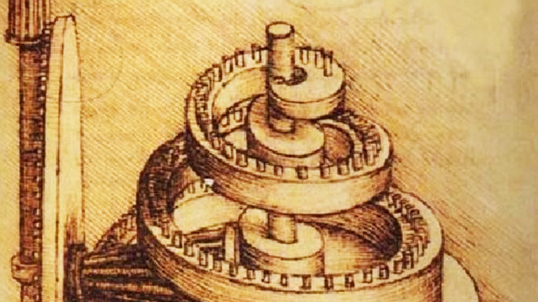
- Gears: Gears are toothed or pegged wheels meshed together to transmit motion and force. In any pair of gears the larger one will rotate more slowly than the smaller one, but will rotate with greater force. Each gear in a series reverses the direction of rotation of the previous gear.
- Bevel Gears: Gears that mesh at an angle change the direction of rotation.
- Worm Gear: A worm gear is a combination of a gear meshed with the threads of a screw. This combination changes the direction of turning motion by ninety degrees. Worm gears also decrease the speed of turning from screw to gear and increase its force.
- Rack and Pinion: A single gear, the pinion, meshes with a sliding toothed rack. This combination converts rotary motion to back and forth motion. Windshield wipers in cars are powered by a rack and pinion mechanism. A small pinion at the base of the wiper meshes with a sliding rack below.
- Cam: A cam is a wheel with shaped bumps on it. Cams are often connected to rods, levers, or springs. In the gravity trip hammer shown here, the bumps on the turning cam push down on the end of the lever making it raise the hammer again and again.
- Crank and Rod: The crank is a wheel with a pivoting arm attached near its edge. The arm is attached by a hinge to a rod. When the crank turns, the rod is pushed back and forth. Alternatively, if the rod is pushed back and forth at the right speed, the crank will turn. The crank and rod shown here are part of giant steam engine.
- Chains and Belts: A chain or belt connects two separated wheels so that one turns, the other will turn in the same direction.
- Ratchet: A ratchet is a device that allows a wheel to turn in only one direction. The ratchet wheel has specially shaped teeth. A bar on a pivot called the "pawl" is fixed above the ratchet wheel. The pawl slides over the teeth of the ratchet in one direction, but blocks the motion of the teeth if the wheel turns in the other direction.
Classroom Activity
Lesson Plan
Main Idea: Close observation and sketching lead to a better understanding of how simple machines work.
Learning Objectives: Observe a gadget closely from several angles while it operates. Identify the elements, the simple machines, that are combined to make the gadgets. Show how the moving parts in machines relate to and affect each other. Create a clear diagram of how a machine works.
Time: approx. 30 minutes with one machine per group
Materials: paper, pencils with erasers, a selection of small machines with visible working parts (the more you have, the better): egg beater, cork screw, car jack, can opener, garlic press, tongs, monkey wrench, hand drill, Vise-Grips, the mechanism from a music box, wind up toy, pencil sharpener, stapler
Teaching Tip: Encourage students to draw systematically, starting at one point and drawing each part and connection in order. Emphasize that this kind of drawing, a machine diagram, should show how the machine works. It is not important that their diagram look exactly like the machine, for example, getting the exact proportions for the parts is less important than showing how they connect to each other. Encourage students to experiment with sketching enlarged views and cut-away views to show parts that are very small or obscured by other parts. Leonardo often left out the casing and structure surrounding machines in his illustrations so he could show the workings more clearly.
Procedure:
- Have students prepare to work in small groups (2-5).
- Provide each group with one gadget to examine in detail. Suggest that students take turns operating the gadget while the others watch to see how each part moves.
- Challenge each group to have a discussion about the gadget. Invite them to investigate their own questions as well.
- Place the gadget at rest so that everyone in the group can see it and distribute paper, pencils, and erasers.
- Students should begin sketching diagrams of their gadgets. They should draw the gadget from their own point of view first. Later they can trade places and draw it from different points of view to show all working parts.
- When the diagrams are completed, students should add arrows and written notes to indicate directions of motion for each part, label the simple machines involved, and explain connections.
- Have students display and explain their diagrams to other groups.
- If time permits, give each group a different gadget to investigate and sketch.
Discussion
What is the function of this gadget? How many moving parts does it have? How are the moving parts connected to each other? What does each moving part do in the gadget? Which parts are simple machines?
Advanced Activity
Ask students to get their parents involved in helping them locate examples of machine diagrams from home. The instructions provided by manufacturers with bicycles, kitchen appliances, tools, and lawn mowers often contain explanatory diagrams to help you understand these machines. Auto repair manuals also contain dozens of these diagrams. Many construction sets such as Lego® and K'NEX® also have similar kinds of diagrams to help you build particular toy designs.
When you have several diagrams from different sources, ask the students to compare them and discuss them using the following questions as starting points:
- What are some similarities and differences between different diagrams?
- Which diagrams do they think are the easiest to understand and the hardest to understand?
- What techniques have the illustrators of the better diagrams used to make their work clearer?
- What techniques can the students apply from these examples to make their own machine diagrams more understandable?